Computer Fluid Dynamics (CFD)
What is Computational Fluid Dynamics?
A general definition is: Computational fluid dynamics (CFD) is the use of computers and numerical techniques to solve problems involving fluid flows.
CFD helps to answer detailed questions about glass making.
Typical problems in the glass industry, ggc is dealing with, are the simulation of the combustion, the batch melting and the flow of the glass melt inside a glass melting furnace. ggc is using several commercial software packages to create two or three dimensional simulations from single flames up to complete glass melting furnaces including fore hearths and regenerators.
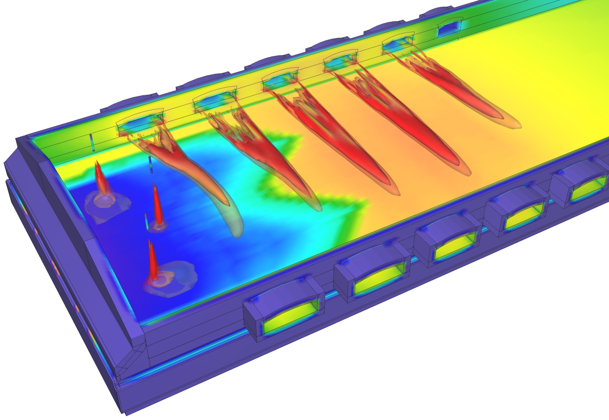
The following picture shows an example of a three dimensional simulation of a side port air- fired float glass tank boosted by 3 roof mounted burners in the zero port area.

Figure 1: Regenerative side-port Furnace boosted by roof mounted burners
A Short Introduction to CFD
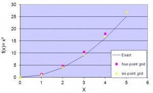
The strategy of CFD is to discretize the continuous problem domain with grid points. This domain can be three, two or one dimensional, but in industrial application mostly three or two dimensional problem appears. The next graph shows an example of an one dimensional problem to explain the principles of CFD.

Figure 2: Strategy of Discretization
In this example (see Figure 2) the continuous problem is discretetized in 4 respectively 6 grid points. In this decretized form a variable is only defined at the grid point. The blue line indicates the exact solution of the function y = x². The dotes show the solution of the different discrete grids. Obviously the solution is more accurate with a finer discretization. But with increasing grid points the effort to get a solution increases too.

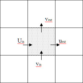
Figure 3: 2D example of the finite Volume Method
Transferring this strategy to higher dimensions we will end up for two dimensional cases with area cells and for 3D cases with a volume grid. The main discretisation methods used are the Finite-Difference Method, Finite-Volume Method and Finite-Element Method. In simulations of glass melting furnaces and combustion, we are using the Finite-Volume Method.
This method is discretising the integral equations directly, so that each grid cell can be seen as a small control volume (look at Figure 3).
Combustion Modelling
Modelling combustion processes requires modelling of flows, reaction and heat transfer. This means that equations for the momentum balance, mass balance and heat balance have to be solved simultaneous. Additionally challenges appears because many physical phenomenas have to be approximated due to technical reasons with simplified approaches. These Technical reason are to less computational power, which effects a to high time consumption or deficient knowledge of the process. Good example are the modelling of turbulent flows or the reaction modelling of combustion.
GGC is paying special attention to the turbulence chemistry interaction. Here ggc is using several own adapted solution like detailed kinetic reaction mechanism for pure Oxygen combustion or state of the art equilibrium assumptions. The spectrum of simulated fuels reaches from Natural Gas over Hydrogen to Oil. The Oxygen concentration in the oxidant varies from 21 to 100 Vol.-%. And GGC is able to model nearly every industrial process.
Glass Furnace Modelling
The modelling of the glass melt is not as complex as modelling the combustion. The glass is treated as a viscose liquid without any reactions. That means only mass transport and the heat transfer is simulated. The heat transfer through Radiation can be approximated with the Rooseland approximation, which introduces effective heat conductivity.
But unfortunately there is also batch in the furnace, and modelling batch is very complex, due to the dependence of the melting behaviour of the batch on the composition, cullet content, water content, grain size of Batch and Cullet and on the heat transfer rates. The effect are not only limited on the flow behaviour, gas releases and the glass forming temperatures but also the reaction paths change.
ggc models nearly every kind of glass melting furnaces. Most of the studies are done to show the benefits from ggc’s technology at specific customer furnaces. With the help of CFD simulations ggc is able to identify the optimal burner position and firing distribution concerning efficiency and glass quality. The spectrum of modelled furnaces contains Air-fired, Oxy-fired and combined Air/Oxy-fired furnaces, different fuels, all kind of glass (clear, all colours, and even ultra clear solar glass) and all kind of products (Container, Fibre, Float).
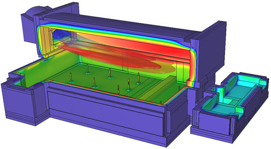
The following Picture show some examples from the work done in the last years.

Figure 4: Regenerative end-port furnace
Validation of the CFD modelling
To ensure high quality CFD simulations, every simulation has to be checked in regard to their reliability. ggc does not only rely on their expert working for long time in the glass industry, but also uses measurements from testing furnaces and from running glass melting furnaces.
The close cooperation with test facilities, Universities and skilled skilled workshops allows to build, test and measure every possible burner design and use the results for improving the CFD- Modelling
Benefits of CFD
CFD has become a powerful tool in combustion and glass melting over the last year for many reasons. One is the dramatic increase of computational power. Every year Workstations with faster CPU and more memory are available at lower costs. But there are others: The Software is improving concerning the handling and the post processing. The mathematic for solving the differential equations becomes faster. The physics and the number of the sub models is improved and more important they are validated against measurements and where weaknesses are found was improved.
Looking at the advantages it lends itself to differ between basic development of equipment and developing of technologies.
In the development of equipment, like burners or nozzles CFD allows to gain insight into the design to optimise. Only parts can be tested and optimized virtually without building the entire combustion test skids, which reduces the development time and costs. Furthermore it is possible to identify improper designs before building and risks during testing prototypes can be reduces. The best way will be designing with CFD and validating later with experiments.
Is the equipment designed, tested and validated, the critical step of integrating the equipment into the process must be done. This step is difficult due to the high complexity of a glass melting furnace. Here CFD is able to answer question about the influences before the installation. It allows to find the optimal process parameter like firing distribution, burner location, thermocouple positions and helps to find critical aspects to watch at during operation. CFD can provide you with information at position, where it is not possible to measure. And CFD can simulate dangerous condition to investigate the consequences.
Up summing, CFD is a widely used tool in designing, testing and integrating of Technologies, which reduces the costs, time and risk whereas it gives at the same time more detailed insight information.
Copies of the validation and case studies are available for glass manufacturers upon request. Please contact us about having your furnace configuration modelled.

